This project turned one of my old Lasko box fans into a simple wind turbine. The main purposes of this project are: (1) have a portable power source to provide small amounts of energy; (2) act as a learning exercise and introduction to wind turbines eventually leading to something bigger. As many have endlessly argued, it really isn't worth the trouble to make one of these outside the stated project goals. A motor designed to run on low energy cannot be practically converted to give out high energy. Mine was made from almost all scrap so cost me little (even buying parts brand new wouldn't be that expensive), but it did require some significant time in research and testing since this is rarely done and fully documented. This page aims to fix that.
The advantages to this project are: (1) a box fan is essentially pre-built with most of the necessary parts and requires little tooling; (2) the smaller size is much easier to handle for experiments and testing; (3) low voltage and current are much safer to handle and cheaper to build experiments with (these can be scaled up for larger projects).
The level of skill required for this project is advanced-beginner. Most of the concepts in this document aren't very hard, but it helps to be able to read schematics and use a multi-meter. An oscilloscope is also a plus for learning. Spend some time on wikipedia learning about wind turbines, generators, and electronics if this is over your head. My fan will be similar if not exact to most other 3 speed box fans, but use your head if yours is a bit different. I've given some extended descriptions to help you figure out something if it is different.
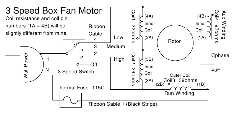
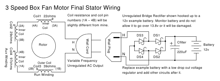
This is the schematic of my motor. It is recommended to print this out and take notes on it as mentioned in the following sections. Your coil resistance and coil pin numbers (1A - 4B) will be slightly different from mine. This is normal and expected. Relabeling your coil pins is recommended at later sections for clarity and simplicity.
Internal Parts Laid Out Close Up 1
Internal Parts Laid Out Close Up 2
Internal Parts Laid Out Close Up 3
Original Motor Wiring 1
Original Motor Wiring 2
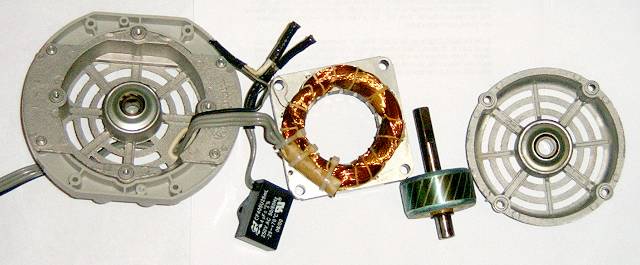
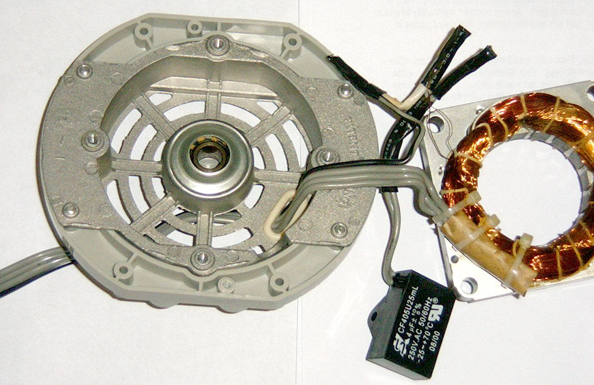
Make sure the box fan is unplugged from the wall and disassemble it down to the motor. Be very careful of the thin magnet wires coming off the stator. These can be easily broken.
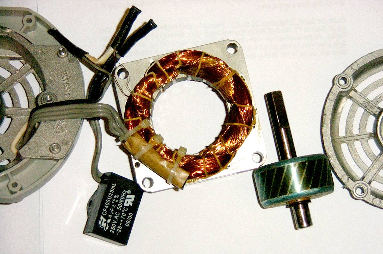
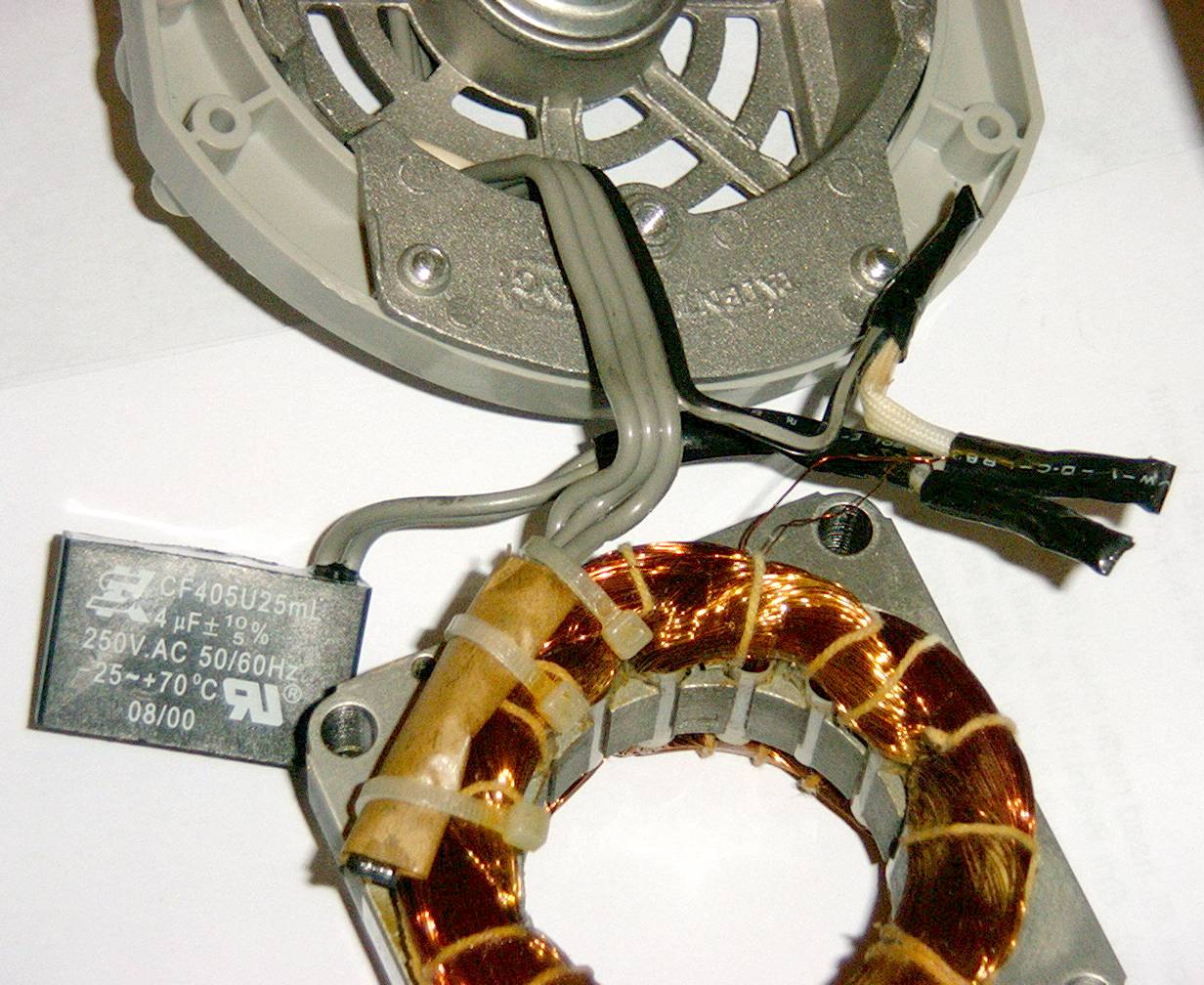
The parts going from left to right...
The thick 4 wire ribbon cable going to the stator comes from the on/off fan speed switch (not shown). This switch isn't needed and can be used for other projects. Cut the 4 wire ribbon cable a few inches from the switch. The wall power cord will go into the opposite side of the switch from where the ribbon cable is plugged in. Cut the wall power cord off a few inches from the switch as we'll be using it later for the power output cable. It is necessary to verify the switch speed settings with the schematic. Strip the short wires around the now freed switch and put the multi-meter in continuity mode (it will beep at low to no resistance). Put a probe on the power cable's neutral wire and the other on the black wire of the ribbon cable. You should always get a beep with this no matter the switch setting. The black ribbon cable wire is #1. Put the speed switch on 3-fastest. Move the power cable probe from neutral to hot and put the ribbon cable probe on the ribbon cable wire by the black one. You should get a beep. This is wire #2. Put the speed switch on 2-medium. Move the ribbon cable probe to the third wire. You should get a beep. This is wire #3. Put the speed switch on 1-slow. Move the ribbon cable probe to the fourth wire. You should get a beep. This is wire #4. If your wiring is different, take note of it on your printed schematic and adapt accordingly.
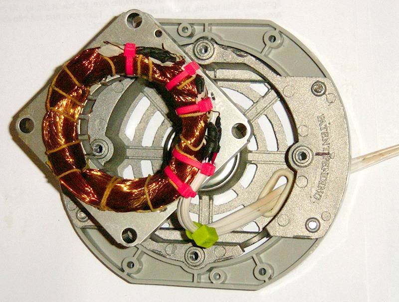
The back mounting plate holds the stator assembly and the back bearing for the rotor (the circular part in the very middle). Using a tissue and some rubbing alcohol, clean the middle opening of the bearing to get rid of any left over oil and crusted up dirt. We'll be re-greasing and re-oiling it at the end.
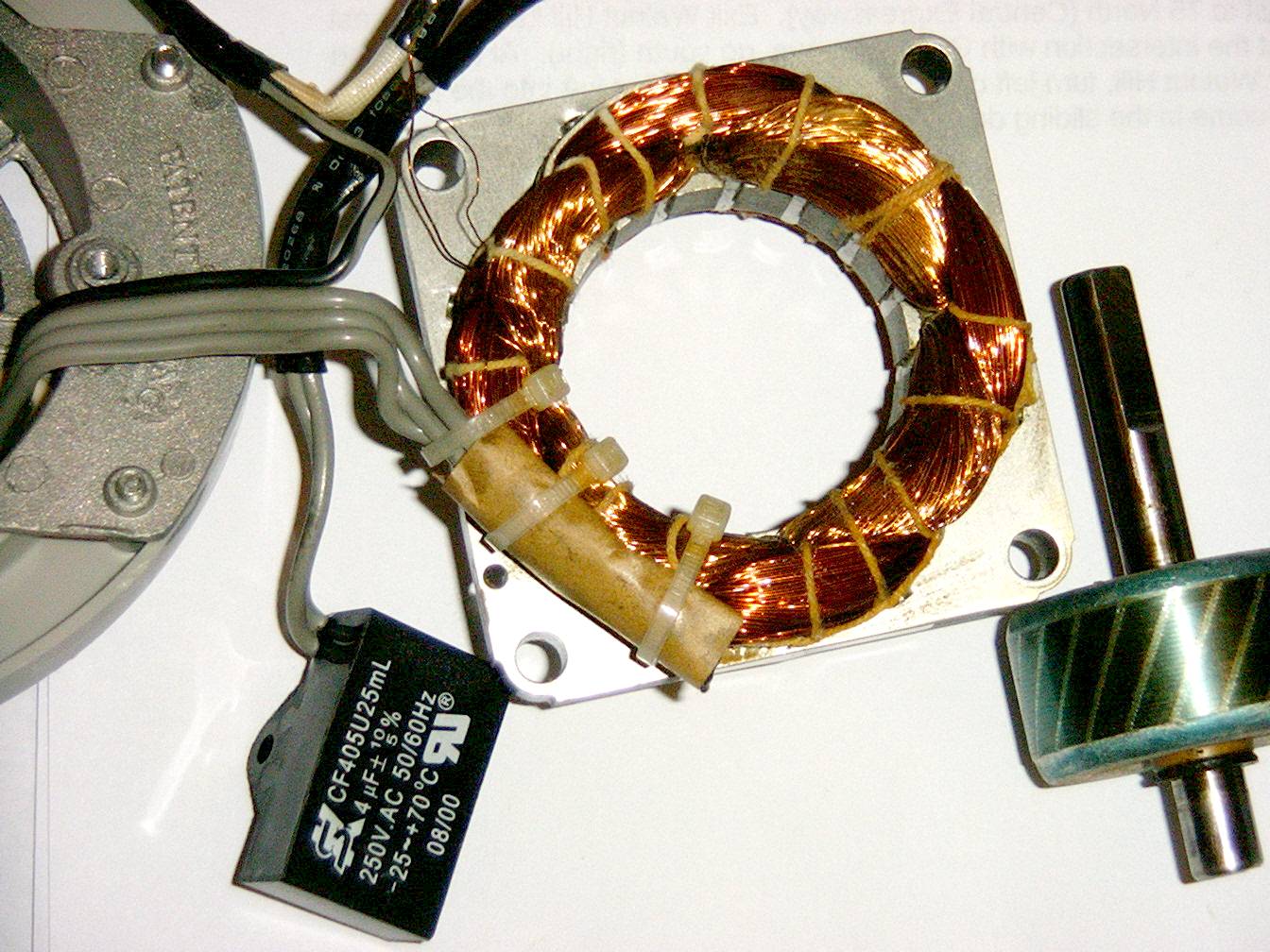
The thick connecting wires of the ribbon cable will need to be totally removed from the stator coils. Be very careful to not break the thin magnet wires or the stator will become useless. Remove any heat shrink and shielding insulating the solder joints. Get some tape and label each pair of magnet wires going to each thicker wire of the ribbon cable from 1-4 starting with the black wire as the key (this will help identify the coils later on if you have a motor like mine, or can help identify the coils for a different motor when searching for a schematic). The 4uF capacitor (bottom black square object) isn't needed any more and can be used in other projects. Some have mistakenly reported that the capacitor acts as an energy reserve for the AC motor. This is not true. When a large bipolar capacitor is wired in series with an AC power source, it provides a phase shift (time delay) to allow the motor to start from a stand still. The white shielded wire in the top left corner of the stator contains a thermal fuse that would "in theory" prevent a fire if the fan was over loaded (see the links section at the end). It isn't needed since the fan will become a turbine and push power out instead of pull power in. (Note that mine fell apart, thanks Lasko quality control.) The remaining 3 thick wires from the speed switch ribbon cable are zip tied to the stator coils. My zip ties had gone brittle and easily broke off (thanks again Lasko). If cutting them loose, be very careful to not cut or nick the coils or the stator will become useless. Once all the removals are done, the stator should be free of any big wires and should have 8 thin magnet wires coming from 4 coils (at least in my 3 speed fan, other speeds will have different amounts).
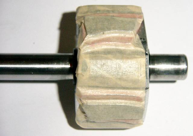
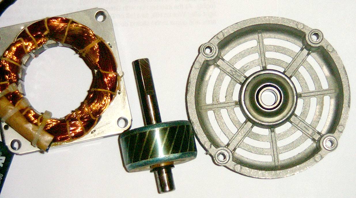
The rotor should easily pull out from the stator assembly. Clean it so there isn't any left over oil or crusted up dirt on it. Make sure the rotor shaft doesn't have scrapes or nicks on it or it will hang and damage the bearings. Rotor shaft damage points can be easily fixed by gently filing them down until the shaft is smooth again. Some beginners get confused and think putting an unmodified AC fan in the wind will magically generate power. This is untrue because of the rotor used. Common AC rotors like this one have no magnets in them that are required for power generation. Instead they are a type of rotating electro magnet that gets its energy from one of the stator coils. When the electro magnetic field from the stator coils meet the generated electro magnetic field from the rotor, there is a push and rotation occurs. For small AC motors (and even some larger ones), this is an efficient and cost effective way of manufacturing. Since there are no brushes like in DC motors, the only real wear points are the 2 bearings.
The top motor cover contains the fan shaft bearing and needs to be cleaned just like the back bearing.
Note: if you have a motor like mine, I once again recommend printing out the schematic and taking notes on it. A consolidated diagram will help make sense of what's going on later.
Generally speaking, the number of stator coils will be the number of magnet wires divided by 2. Center taps in cheaper motors like this one are usually made by soldering the ends of 2 coils together. If the number of magnet wires coming out of the stator is odd, you'll have to do some extra work to figure out why (but it was probably a center tap wound into the coil with only 1 wire).
You should have already numbered the magnet wire pairs from 1-4 based on the thicker ribbon cable wires coming from the speed switch. Pick a wire from each pair, use a small piece of tape, and label it wire 'A'. It really doesn't matter which is 'A' in each pair so long as the wires aren't carelessly relabeled later. The unlabeled wire will be denoted as 'B' (or you can label it with tape if you want). This will be used to find coil polarities towards the end.
Put your meter in resistance mode to get an ohm value. Hook one probe up to magnet wire 1A and check all the other wires starting with 1B until 4B with the other probe. If each coil is isolated like mine, there will be only one response somewhere down the sequence. Take note of each magnet wire label and the resistance of the coil. Example: mine was 1A-4B at 97ohms (Coil4 in my schematic).
Continue down the wire numbering sequence until you reach the end and take note of the readings. While it may seem excessive, it is important to test each wire to avoid "surprises" like a hidden center tap or 2 coils shorted out. Accurate mapping must be done so the coils can be properly wired for the most power towards the end. If a coil or two turns out bad, it must be left out of the final stator wiring. This will reduce power and may not be worth continuing with a damaged motor.
With my stator comparing it to the schematic, the coils were sorted from lowest to highest resistance. This means Coil1 had the least resistance, Coil2 had the second least resistance, and so on. Label "Coil1" through "Coil4" in your notes based on this.
If your motor is like mine, you now have enough information to relabel the coils like my schematic if you want to. It will make things easier to understand later on. If you look closely, my Coil1 is using wires 3x and 4x, Coil2 is using 2x-3x, Coil3 is using 2x-1x, and Coil4 is using 1x-4x. Your coils should be using the same unique wire pairs. Now that you know this, the A and B wires can be relabeled to match my schematic on your motor.
Once the coils are mapped out, it's helpful to know where each coil physically is in that big mass of wire known as the stator. My stator has 2 bunches of coils. One is offset from the other (generally meaning it is out of phase by some amount). It's a little hard to see in the pictures, but you can pick it out if you use one of the bigger pictures and look closely. By looking at the wire mass, it's impossible to know which bunch holds which coils.
Thankfully there is a way to get a rough idea. Find a power supply or old wall wart that can supply 20-40 volts AC or DC. Take some jumper wires and hook it up to the first coil. Power flowing through resistance will create heat. My power supply wasn't very strong so it took a few minutes for the coil to heat up in the bunch. Once it did, it was relatively easy to feel for the heat in the bunch and write down its location. Once found, unhook the power supply and put a fan on the stator to cool it down for a few minutes. Repeat for each coil.
As a safety warning, don't put the power supply on a coil with a resistance less than 15 ohms. It could overload the power supply and damage it. A lower voltage power supply with a higher amps rating could be used, but it may not like it either and be damaged.
As already noted, the rotor lacks magnets for electricity generation. While any magnets could be used in theory for electricity generation, this project is kinda pointless using weak magnets since this is already a low power motor that won't put out much. Neodymium magnets must be used.
When choosing, buying, or salvaging, the magnet's north and south poles should be on the larger flat sides. A bar magnet with the north pole at one end of the rectangle and the south pole at the other will not work properly. For that bar magnet to work properly, the north and south poles must be on the larger faces.
Since this project is physically small, we'll be using 4 magnets, 1 per main coil. For this type of project, more are typically used if the motor is larger. Ideally north and south pole pairs should line up with the metal coming between the coils to the rotor. This metal acts as a magnetic flux guide for the coils. In most motors like this, 2 norths will go to the flux guides in the middle of the coil, and 2 souths will complete the flux guides on the outsides of the coil. The magnetic metal in the rotor completes the flux path on the other side. The metal magnetic flux guides act like a regular wired circuit for magnets. The rotor is a bit small in this instance and getting small high powered magnets attached to it would be even more difficult. The standard alternating north south configuration showed and used for this project is adequate for demonstration and testing. On larger motors, this can be optomized as mentioned before (like ceiling fan mods).
I used salvaged neodymium magnets from dead hard disks in my project. I figured filing down the rotor into a square shape wouldn't be that hard. I was wrong. The top and bottom aluminum caps are easy enough to hand file, but the hardened steel plates (rotationally offset forming the "////" pattern along the middle cylinder) took several hours on a grinder with a new wheel to flatten into a square shape. I'm not doing that again.
Another guy (link at the bottom) used a power drill and round magnets in his rotor. This is the method I recommend as my drill made mounting holes fairly easy. Get as thick and wide cylindrical magnets as you can afford and that will fit in the rotor. Start by equally marking the 4 sides of the rotor. Looking down the shaft, each drill point should be 90 degrees apart and in the middle of the rotor's steel plates. Use a small drill bit to start a pilot hole. Increase the drill bit size gradually to avoid over heating the bit and over loading the drill motor. This method will also make for a more accurate and cleaner hole. Don't rush this part as it is important for the final electricity generation. Do not drill so deep as to hit the rotor shaft. Drill just deep enough that the round magnet will fit in the drill hole, and the top of the magnet is flush with the outer diameter of the rotor. The sides of the cylindrical magnet will still be sitcking out. Those will be fixed after gluing. (I recommend taping the magnets in place and doing the rotor testing section as mentioned below before gluing the magnets permanently in place.) Once all 4 holes are done, epoxy the magnets in and let them dry for a day. After secured, file off the parts of the magnet that stick out past the outer diameter of the rotor, so the rotor cylinder is flush all the way around. The key is to get the magnets as close as possible to the stator coils to get as much power out of them as possible. (Some of this will make more sense after reading the Rotor section.)
Neodymium Safety Warning: These are very strong magnets and can easily injure human flesh. Flesh in between 2 magnets can be pinched very hard or even crushed by larger magnets. Bringing one magnet towards another magnet on a table can cause the table magnet to jump towards it, strike it very hard, and shatter both sending shards everywhere. Even one of my little thin hard disk magnets took a flying leap 6 inches away and broke one of my magnets on my rotor. BE CAREFUL!
If you're a masochist and squared off the rotor for flat magnets like I did, follow this section carefully. If you've used round magnets mentioned above, some of this will apply to you, some not. Use your head and merge it together as needed.
The magnet polarities for this motor rotor and most others like it will be north-south-north-south (each side of the rotor will alternate magnetic polarity). To determine magnet polarity, get a compass and the north arrow will point towards the magnet's south pole. Shouldn't it point to the north pole, you say? There's actually a very deep and dark secret kept by the various cabals of this world: this planet is upside down. Be careful about spreading this knowledge as people have been known to "disappear". But I digress, the planetary north pole is actually the magnetic south pole. This means the compass north arrow is actually attracted to magnetic south.
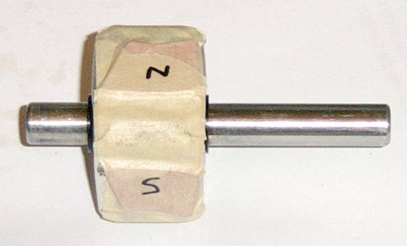
Initial Testing. Since the rotor has steel in it, the magnets will stick to it fairly well. They still need to be secured with tape, though. Carefully push down the tape along each intersection so the magnets cannot slide around.
I used this testing method to make sure I had the magnetic polarities correct and was generating power. Put the stator on its back mounting plate, insert the rotor carefully (the magnets in the rotor will pull towards the metal in the stator), make sure the magnet wires from the 4 coils are sticking out, attach the top motor cover, and make sure all the parts lined up as the tolerances are very tight. Attach the plastic fan to the rotor. The fan should spin freely with a little bit of cogging from the magnets. The rotor should not be rubbing or grinding against anything. If it does, stop here, take the top motor cover off and fix the problem. Using alligator clips on the meter probes, attach the probes to Coil1 and set the meter to AC voltage. Give the fan a medium-hard spin. The meter should report around 1v (at least for my setup). Set the meter to amp mode and give the fan another spin. The meter should report around 30mA (once again for my setup). Continue metering the other 3 coils to verify operation. My Coils3-4 would report a few volts each (more windings showing a higher resistance).
As a side note, I also tested the magnet polarities on the rotor in the following configurations: north-north-south-south and north-north-north-north. These configurations gave me far less than 1v AC and 1-2mA. These are abysmal numbers. If you get these numbers in your tests, grab a compass and double check the magnet polarities on the rotor.
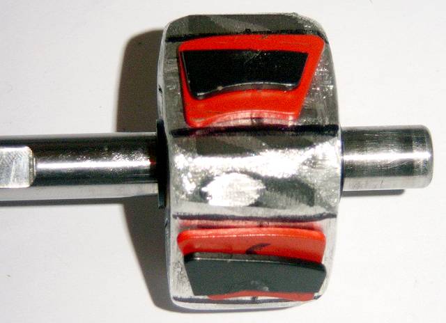
The closer the magnets are to the stator coils, the more power they will deliver. This is why the rotor has such tight tolerances to the stator and why the two are so close to each other. When I took some extra flat magnets, broke them in half, and added them on top of the existing magnets (black on top of red), I got a significant power increase.
For testing, the magnets need to be taped down just like in the previous test segment.
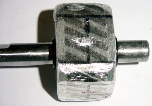
Small drill holes were added to give the epoxy an extra grip for the final gluing stage. Alignment marks were also drawn to make sure the magnets centered up on the rotor shaft properly.
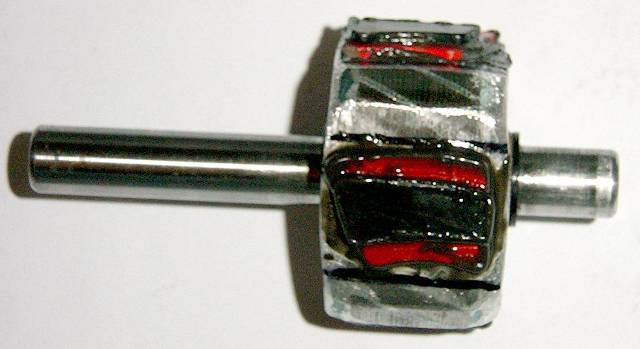
Magnets epoxied to the rotor. The grounded metal is fairly smooth. Be sure to work the epoxy in with a tooth pick so it will have mechanical strength when it dries. Epoxy around the edges of each magnet to also give it some gripping mechanical strength. Be sure to work the epoxy in along the broken edge of the top magnet. Magnets will easily corrode over time and need a protective coating. Spreading the epoxy over the entire magnets is a good idea if the running environment will be wet or corrosive. Also be sure to fully coat the magnets with epoxy on the bottom (as opposed to just the sides only) as it forms a protective layer to keep the magnets from rubbing against the metal, breaking through their protective coating, and oxidizing, which would make them useless after a time.
Generally speaking, the 4 coils in the stator have 3 possibilities: 100% in phase, 100% out of phase, and an offset phase. When using coils together, it is very important to determine the phasing relative to the other coils. For example, adding a coil that's 100% out of phase to another coil will essentially cancel out both of the coils and no power will be produced. A coil that's 100% in phase will add power to the coil.
By this point each coil should be identified with the 1A to 4B pin notation. Looking at the schematic, the dot on the coil (inductor) symbol will be assumed to be the starting point of the coil winding. Think of the dot as being similar to the + sign on a AA battery. Since this is AC, for starting out it really doesn't matter where the dot is so long as the other dots are consistent with the first.
I'll send out the reminder again that the numbers on my schematic will be slightly different from yours. If you want to relabel your wires to match mine after all this, that's fine. It may be a little less confusing that way. If you have already relabeled your motor to my schematic, doing all this is still important to verify that you have what you really think you have.
Re-assemble the fan motor with the thin magnet wires sticking out. Be careful to not break the magnet wires. Put the plastic fan blade assembly on and give it a spin. Make sure it spins freely and it isn't making rubbing or grinding noises.
We'll set all the coil phases relative to Coil1. On my schematic, pin 3A has the dot and 4A is the other end. On your wires, 3A or 3B should belong to Coil1's start winding. Mark this down on your schematic print out as the Coil1 dot pin.
Get your multi-meter and set it to AC voltage mode (this also works with amp readings if your meter has it and you want to double verify). We are now going to parallel Coil1 and Coil2 to see the response. On my schematic this means 3A will connect to 2A and 4A will connect to 3B. Since you don't know the polarity of your Coil2 yet, try matching the coil with your 2x-3x in that order. Connect a meter probe to each wire pair and give the fan a good spin. If all goes well you'll see a voltage reading. This means Coil1 and Coil2 are in phase. Mark your Coil2 pin number (the wire that is connected to Coil1's 3x) next to the dot on your printed schematic. If you get no reading this means that Coil1 and Coil2 are out of phase (backwards in this case, but make sure you first have the correct Coil2). For completeness sake, reverse Coil2's wires from 2x-3x to 3x-2x. Give the fan a good spin again and watch the meter. This time there shouldn't be any voltage reading, meaning the coils are out of phase. We just verified both ways, so we can move on to the next coil. On my motor Coil4 will give 100% out of phase or in phase responses just like Coil2. Go back to the beginning of this paragraph and repeat the steps for paralleling Coil1 with Coil4.
On my motor, Coil3 is the outer coil and is slightly out of phase with Coil1, Coil2, and Coil4. Thankfully this phasing isn't too bad and Coil3 can still be used instead of wasted. Go back to the previous paragraph and parallel Coil1 with Coil3. Note that it will give the same voltage reading both forward and reversed. Since we get a response both ways, I'm not sure where to put Coil3's polarity dot, but I put it on wire 2B (2x in your case). It really doesn't matter as Coil3 can be used in either direction.
If you're trying all this on a different motor than mine and getting very different results, you need to draw a table on a sheet of paper on test each coil against each other both forward and reversed. From there you're going to have to make some arbitrary decisions about what should go where. Don't rush these polarity tests as a screw up will make the data even more confusing.
If you have an oscilloscope, it can come in very handy here. The scope will show the wave form coming out of each coil. It will probably look like a lumpy sine wave. This is to be expected with a home brew generator. Paralleling 2 coils like in the instructions above will show some significant information. If the wave form looks just like before but larger, the 2 coils are 100% in phase. If the wave form looks much smaller or disappears, the coils are 100% out of phase. If the wave form looks like a lumpy mutant of the 2, then the phasing is offset by some amount. If the wave form is still mostly sine wave looking, then the 2 coils can probably be used together. If the wave form looks really bad, then those 2 coils cannot be used together.
A single phase motor will have a single phase output. This is just like normal 120/240v AC wall power since the box fan used to be fed from normal wall power. For beginners this makes things a bit easier to understand.
Each coil could be wired up separately for 4 independent power supplies, but this is a very low voltage and low current project. It isn't worth it. In the future, other projects with bigger coils and magnets might justify this, though.
As noted earlier, Coil1, Coil2, and Coil4 are 100% in phase (all in the inner coil winding) and Coil3 is slightly out of phase (outer coil winding). Coil3's phase is close enough to use with the others.
All the coils could be put in parallel for higher amperes, but that would average the generated voltage and lower it to something unusable. A mixture of series and parallel could be wired, but once again the output voltage would be too low. We will wire all 4 coils in series for highest usable voltage. This may sound like a bit of a waste, but keep in mind that low amperes going into a higher load will pull down the working voltage and still provide about the same power if the coils were wired differently.
When wiring all coils in series, use the coil's dot symbol like the + symbol on an AA battery. Since there are 4 coils, this will be like putting 4 AA batteries end to end. Note that on the new "Final Stator Wiring" schematic, this is exactly what has been done.
Fire up the soldering iron and prepare to solder all the stator coils in series according to the new schematic. Note that the coil pin numbers (1A to 4B) have been transferred to the new schematic. If you use different pin numbers, be sure to change them on your printed copy. Take your time and solder the magnet wires together very carefully. Finding the right wire can get a bit confusing at times.
As mentioned earlier, I re-used the AC power cord as an output cord from the stator. Be very careful soldering it to the magnet wires as it can pull on them pretty hard and break them. Be sure to thread the power cord through the stator back mounting plate hole before soldering it. In my schematic, 3A goes to hot and 1B goes to neutral. Since this is AC, it really doesn't matter which is hot and neutral if you can't tell on your cord or your cord isn't keyed.
Wall Cord Warning. I re-use the wall cord as it's already there, has a male connector on the end, and has cheap female connectors. I can also use cheap pre-made extension cords for a longer cable run. Be sure to label the plug "Generator Output" and DO NOT EVER plug it into a real wall sockt. It will start a fire and destroy the motor (and maybe even burn down the house killing people). If you're careless, live with someone who's careless, or have small children around, cut the male wall connector off the cord and use a different connector set. Don't take the safety risk.
Once all the soldering is done, wrap each solder joint in electrical tape to prevent any short outs. Get some small zip ties (shown in red in my picture) and carefully fold the wires down and secure them in place. Start with the power output cord as it has to go through the hole in the stator back mounting plate. This might take a few tries to get it properly aligned, so watch how the stator mounts to the back plate carefully. After the power cord is finished, the rest of the magnet wires are pretty easy to do. Just be careful to not break them. A strain relief for the power cord was made using the green zip tie. There isn't a lot of room, so mount the stator to the back plate, push the power cord in a little bit, and mark the location on the cable.
Tesla Vs. Edison. As the new schematic shows, I run AC out the power cord because it can go longer with normal wire suffering fewer losses. DC requires absurdly thick wire to go the same distance. This is why wall power is AC and is transmitted as high voltage AC along power lines. The argument to use AC or DC goes back to the early 1900's (hence this paragraph's title). I have trouble understanding why "professional engineers" design "commercial" wind turbines to have DC out on the back of the turbine. As many have already argued, running DC to a house is safer in a wet outdoor environment... But at the same time, many homes get their AC power delivered to the side of the house from a pole high up in the air. The AC power from a wind turbine should be no different. If you run either your AC or DC power lines along the ground in the wet mud, maybe you deserve to win the "Darwin Awards".
Because of DC line losses, I put the diode bridge and filter capacitor close to where I use them. In the schematic, I use schottky diodes as these have less of a loss than straight rectifier diodes. Schottky diodes are available in high power versions, so there's no reason to not use them on high power projects. Most people will size the filter capacitor at 1-3uF per milli-amp output (or 1-3mF per amp output). The parts need to be rated above the highest working voltage than can come out of the turbine generator. Usually +30-50% is a reasonable number. If the turbine generator produces a low output, it's easy to go a few times the working voltage for hardly any extra cost. If the diode bridge and filter capacitor are outside in the hot summer (like in a shed), be sure to get a heat tolerant capacitor. The diode bridge may also require thermal grease and a heat sink.
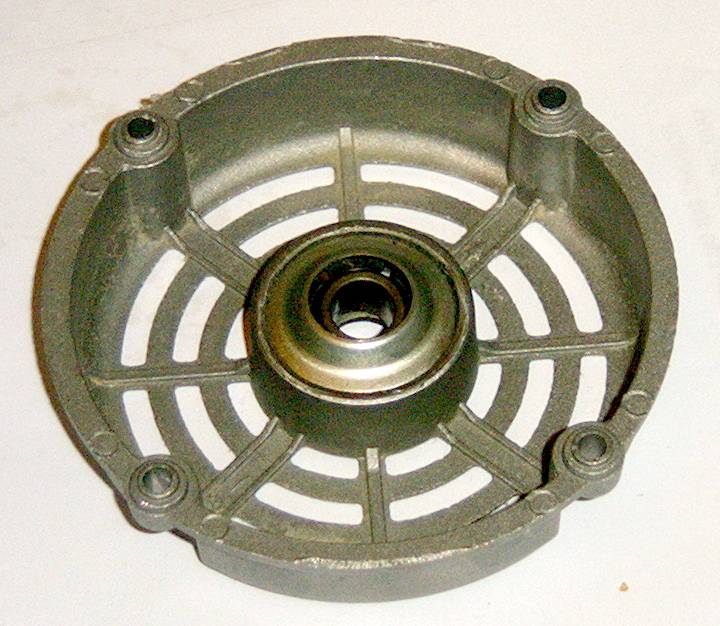
For final assembly, both bearings need to be lubricated. Look closely at the picture of the bearing. In the center is the central ring that can move freely (this is what holds the rotor shaft in place). Between that ring and under the top cover is a gap that contains a sponge material to hold oil (not easily seen). If the bearing hasn't been oiled recently, get a can of 3-in-1 oil and put 4-8 drops equally around that gap. Rotate the bearing assembly around so the oil gets absorbed into the sponge material evenly. Holding a tissue or paper towel over the holes while moving it around will catch any excess spillage. For the inside of the ring and the rotor shaft, get some white lithium grease and a cotton swab and spread a little around on the inside of the ring and the rotor shaft close to the rotor assembly.
At this point, everything is done. Re-assemble the motor (still being careful of the magnet wires). Attach the motor back to the fan frame. Push the plastic fan assembly back on the motor. Give it a good spin. It should rotate freely without any scraping or grinding noise. The box fan turned wind turbine is complete and now ready for use.
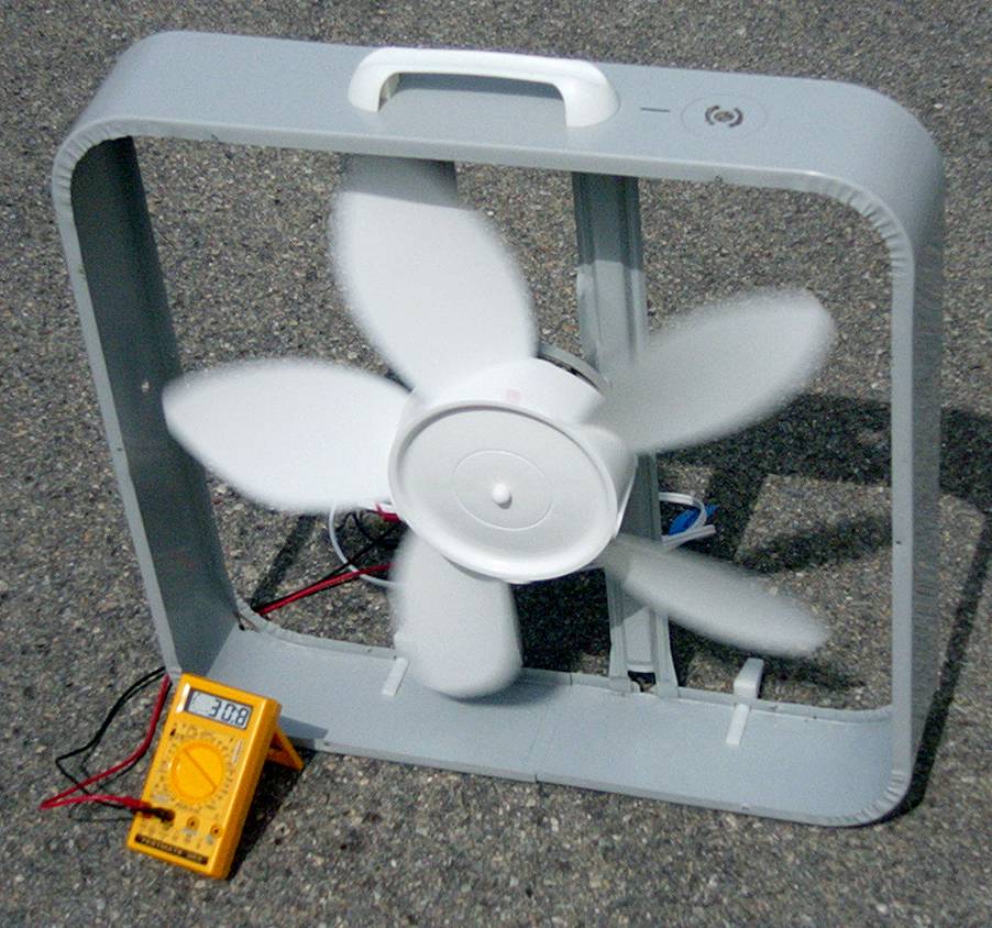
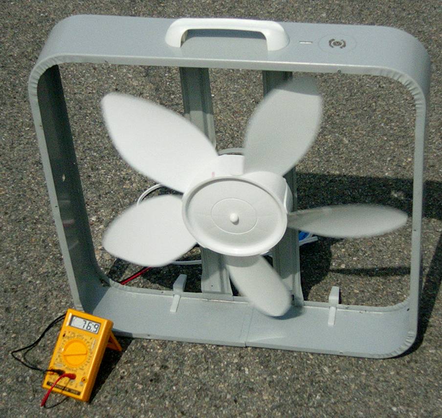
Not surprisingly, running a wind turbine on the ground is mediocre for wind (especially in a neighborhood with a lot of houses and trees). For medium speeds I'd get 25-30v unloaded (first picture) and around 75mA shorted out in amp meter mode (second picture). For normal running with a circuit attached, the voltage would likely be lower under load and the available amperes would be a little less since the voltage potential wouldn't be from the available amount to ground. If the turbine had a tail fin and was mounted on a small tower which was allowed to spin freely, it would be much better. All in all, still not too bad for recycled parts.
Some box fans come with a special molded wall plug that includes a non-replacable fuse. Sometimes these are labeled, sometimes not. If the power cord shows up as broken when metering, and it really isn't, cut off the plug and replace it.
A fuse/circuit breaker could be added to this design, but the power output is so low that it's not strong enough to blow anything.
A step up transformer could be added to increase the voltage at the cost of amperes. In this case it could be a normal step down transformer reversed. Transformers aren't 100% efficient, so there will be some power loss. Most are around the 80% efficient range. Transformers are optimized for the 50-60Hz frequency. While they will operate above and below those frequencies, the output may not be optimal.
A monitoring MCU could be connected to the Vout of the diode bridge assembly and use to log wind output information over a longer period of time. This might give a bit more realistic data than an anemometer as it provides a more realistic load. Adding a tail fin, a swivel mount, and a digital compass would allow for wind direction information.
An electronic brake that shorts out the coils to slow down the fan blades in an excessively high wind situation doesn't really work well in this design as the power generated is so little. It will respond, but not very much.
An idea for a electronic brake would be to add another diode bridge and filter capacitor and hook it directly up to a small relay through a current limiting resistor. Trial and error would have to be used to determine the resistor's size to only activate the relay during a high voltage / high wind situation. The filter cap would need to be large enough to provide a little hysteresis so the brake relay wouldn't oscillate at the transition wind speed. The down side to this simple design is that the relay coil is always pulling some amount of power and isn't very efficient.
The simple relay idea could be expanded to a small control circuit using a zener diode for the voltage level and a transistor to activate the relay coil. This has probably already been done somewhere.
Another over spin safety feature could be done with a servo connected directly under the tail fin to rotate the tail fin and thus the fan blades out of the wind. This is a more complex design and would require an MCU. The servo would have to be mounted close to the front of the tail fin as the wind pressure would fight the servo movement and potentially break it or burn it out.
Water Resisting. This can be accomplished by dipping the rotor and stator into some kind of water sealer (spar urethan? laquer?). The parts would likely need some kind of cleaning first (clean rising soap or degreaser with a good rinse). Each of these parts don't move but will move when put together. This means the rotor shaft can't be made any thicker with a layer of sealer. The main key here is to not build up any layers that would end up grinding against each other.
Water Proofing. This can be done using 2 inch wide masking tape to cover the holes and putting a layer of silicon caulk over that to form a kind of rubber jacket. A drain hole would need to be added to the bottom. The front rotor shaft could be sealed up fairly well by adding a thin layer of tape to wrap around the rotor shaft at the caulk intersection point. After the caulk dries, the tape would be removed and a thin layer of grease added to that part of the rotor. The main issue is how to seal up the motor body in such a way it can still be opened at a later date. At the very least, the bearings would need servicing at some point in the future.
Shaded Pole / C-Frame Motors. These are the types of motors found in small desk fans. They're designed for very low power, which they're good at. This also means they cannot produce a lot of power if modified. I'm unsure if they'll ever work as a generator since they don't have stator coils. The rotor is usually the same one used in a box fan (pictured at the top) and can be drilled for magnets using the instructions above. All in all, I'd say these aren't even worth looking into. If your shaded pole motor has problems (which they often do), fix it by cleaning out the dust and dirt and re-lubricating the bearings using the instructions above. With a little regular maintenance, these motors will last a very long time.
Towers. For this project, towers are overkill. Duct taping the fan frame to a stool might be worth it, though. If you do end up with a tower mount, make sure the power output cord is mounted to a brush coupler to keep it from getting overly twisted and breaking something. A small tower mount could be made from PVC since this project is so light weight. The tail fin should be some large fractional size of the fan blades. It will also need some kind of lightning protection.
Paint. This is overkill for such a small generator unless you use it outside for long periods of time. Plastic doesn't always stand up very well to ultra violet light from the sun. A layer of exterior paint can add a lot of protection. If paint is done for show, I recommend gloss black and Ferrari red.